
Adventures installing Prusa INDX with LLM help
NOTE: Some of the photos are taken from the Prusa official guides and belong to them.
In the last couple of weeks I’ve been working on upgrading my 3d printer. I have a Core One that I assembled from a kit, and I got an upgrade kit that includes the INDX and Gen2 upgrades.
This hardware is new (I preordered it), so it contains a wonderland of undiscovered problems.
What’s in the box
Gen2 involved some quality-of-life upgrades for the printer itself - finer gear bands (more teeth, allowing for more accurate movement), different bed spacers (shorter bed heat time).
INDX involved replacing the print head completely.
The head is in charge of drawing in the filament, heating it, pushing the melted filament onto the bed, then cooling it a little.
The INDX head is composed of a single “active” part (that contains the motors, heater, sensors, fans), and 8 “passive” parts that only have the filament passing through them and are grabbed by the active part. I think about it like a hand and multiple pens - the printer only has one complex part, but can quickly grab a pen, write with it, then put it back.
My INDX printing, alternating between pink and black
This is in contrast to the MMU units, where there was a single head that unloaded one filament and loaded another. The unloading part was a new process for the printer and had its own failure modes (e.g. hotend generates a blob too thick for the gears).
The two upgrades can be installed sequentially, but they both involve taking the printer apart to a certain degree, so Prusa created a meta-guide. It’s a single page guiding you on how to hop between the Gen2 guide and the INDX guide (“start from step 2.40, get back here after 2.76”) to do both at the same time. This made the upgrade even more complicated, which it already was as it involved taking working things apart and not just greenfield construction.
Assembly
I recently had a positive experience with applying LLMs to non-programming, yes-engineering tasks. I decided to test it by having it:
- Download the meta guide, the INDX guide, the Gen2 guide
- Reformat them in a convenient-for-it way on the disk
- Load the entire guide into its context window
I tried having it create its own version of the meta guide that is less confusing, but it didn’t work very well. The result wasn’t bad, it just wasn’t that much better than the original.
I found it knowing the guide useful for other reasons:
“Will I need this screw again?”
Some of the instructions referred to screws “you removed earlier”. How earlier? Unclear. When I remove a screw, do I keep it or does it go to the big-bag-of-screws never to be seen again?
I got used to asking the LLM:
gen2 3.5. - do I keep the screws?
indx 4.3 - do I keep the nextruder holder screws?
indx 4.15. “Ensure that the four highlighted holes are empty…” keep screws I find there?
“Can I do X now?”
Being a smarty-pants, I sometimes wanted to do things not in the way the guide instructed because it made more sense to me.
indx 4.35. when do I connect the x,y motors I disconnected in gen2 upgrade? can I do it now?
can I move the dockside fan installation forward? or should I do electronics first?
Since the LLM held the whole guide in the context window, it could answer whether reordering the stages would make things easier or more complex for me.
Troubleshooting
After the assembly was complete, the time came to actually test and use it. Since the LLM already had context, I used it for troubleshooting the calibration and testing process. I then added a new layer by having it clone the printer’s firmware (Prusa-Firmware-Buddy) so it can authoritatively answer where errors come from and what the printer is trying to do.
Some things were not interesting, but some were very much so.
Too many teeth
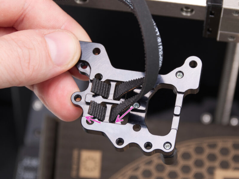
Photo: Prusa
One of the hardest parts in the Prusa Core One printer is attaching the belts to the head carriage. It involves grabbing 4 belt ends, inserting each one through two holes, then screwing the carriage to another piece in a way that squashes the belt ends, holding them in place. Turns out that although I did this part in the Core One assembly 5 times, I didn’t learn enough for this to go smoothly.
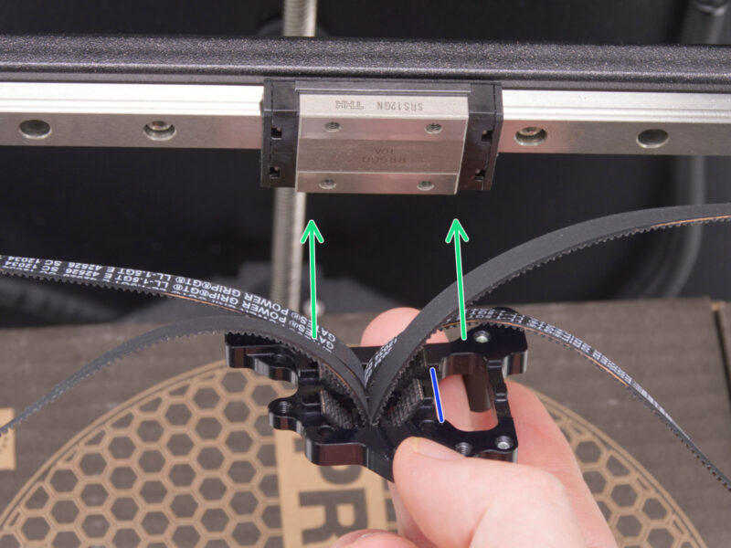
Photo: Prusa
The printer has a new “squareness” test, where it checks that moving between all of the head’s range (back-left to back-right to forward-right to forward-left) generates a shape of a square. This test failed, hinting at “something wrong with the belts”. I told the LLM about the error message, and it went looking for what the squareness check actually does, and what I could have done to fail it. After ensuring there are no twists, I told the LLM that it has to be my fault somehow, and is it possible I did the holder wrong. It replied that unevenness in the teeth grabbed in the holder can manifest exactly like that, and suggested I take the holder apart. Turns out that on one side, the bottom belt had 5 teeth inserted, and the top one had 6. The guide doesn’t mention the “equality” part at all. Obviously that was the problem, and after meticulously ensuring 5 teeth in every part of the holder, squareness passed great.
Bad bed
Before a print starts, the printer checks the height of the bed (the printing surface) on several points. Usually it’s something like a grid of 7 * 7 points under the printed object. It does so because the bed is not absolutely flat due to minute imperfections, dust trapped beneath the printing sheet etc, and knowing how the bed curves lets the printer compensate for that during the print itself.
One of my prints failed on this leveling check. The middle check came out 0.5mm taller than one of the edges (which is a lot for this kind of an engineered flat surface), and the contact was “soft”, which in human speak means the surface had some yield to it. Since this worked before my meddling, I had the LLM identify screws that I worked on during the upgrade. Using its knowledge of what I did, it directed me to specific screws and how tight they need to be (based on what they actually do).
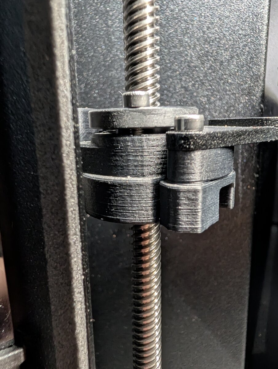
If you have a sharp eye (I didn’t at the time) you could see that the black disk on the top is not fully adhering to the rest of the black mass. That disk keeps the front-left side from moving upwards, and without the screws holding it in place, the bed did indeed escape upwards.
After tightening them, the bed worked perfectly with both the textured sheets, and the smooth ones too.
Mystery loadcell failure
In 3d-printing there’s a concept of “first layer offset”, which is the initial distance of the print head (that extrudes the material) to the bed (where the object is being printed). Just like when writing with a brush, you can’t be so far that the paint just falls off and drips, but you also can’t be so close that you’ll smear the paint. You need a sort of light touch, and in the first 3d-printers the tuning was more of an art than a science. The newer Prusa printers come with a “loadcell”, which measures how much force is applied on the head from the bottom, indicating how hard it’s “touching” the bed. Using this device, the printer can self-calibrate at the start of each print, for each of the tools (as I have 8 of those “pens” now, each with its own tiny difference in shape and alignment), to find the ideal distance from the bed.
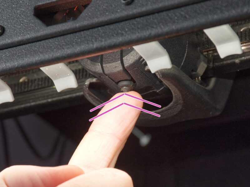
Photo: Prusa
I had a weird problem where printer calibrations done outside of a print would complete successfully. The bed would get closer and closer to the head (in my printer it’s the bed that goes up, not the head that goes down) until it’s just-touching, then move on to the next tool or conclude happily.
When actually starting a print and doing the exact same procedure, the printer would stop the bed when it’s a big distance (3cm) from the head, hesitate, try a bit lower, rethink its life choices, then often fail. The failure was justified as the printer got multiple results indicating wildly different heights (expected variance between checks is under 1mm), so something’s obviously wrong. Sometimes it’d retry, sometimes I’d have it retry, and overall most of the prints failed several times on this.
The LLM enabled some diagnostic output on the printer (which required me to connect it over ethernet to its OctoPi companion) and confirmed the loadcell is getting crazy readings. Its initial assumption was that during printing the printer is quicker to act after picking up the tools, causing “ringing” (vibrations from the pickup that disturbed the electronics), and it suggested waiting a bit more with more retries. It generated a custom firmware we flashed to the printer and we tried again.
It worked a bit better, but mostly because there was more retrying, so better chance of randomly getting a good result. I wasn’t happy with this solution and wanted to continue troubleshooting. “If ringing is the problem, we can wait for 30 seconds after a tool change and it’ll settle”, I suggested. We tested it and the ringing theory didn’t hold.
After that, the LLM wanted to run convoluted tests on the printer that involved picking up, returning, waiting on the printer via its usb connection. It was thwarted by the printer itself getting bored after 5 seconds of not getting instructions, and treating it as a “printing finished”, cleaning the nozzle and putting it away, which ruined the testing. Reading the firmware, the LLM had me disable “serial printing screen” (which is a spooky internal setting), which means the printer didn’t have the concept of cleanup anymore, so the LLM could send whatever it wanted.
We couldn’t reproduce the problem anymore, and the LLM suggested “the printer is warmed up after all the testing, so no ringing and you can print what you want”, so I did and it worked.
The main downside was that because the printer didn’t treat this like a print, it didn’t turn on all of its lights so I couldn’t really see what’s going on.
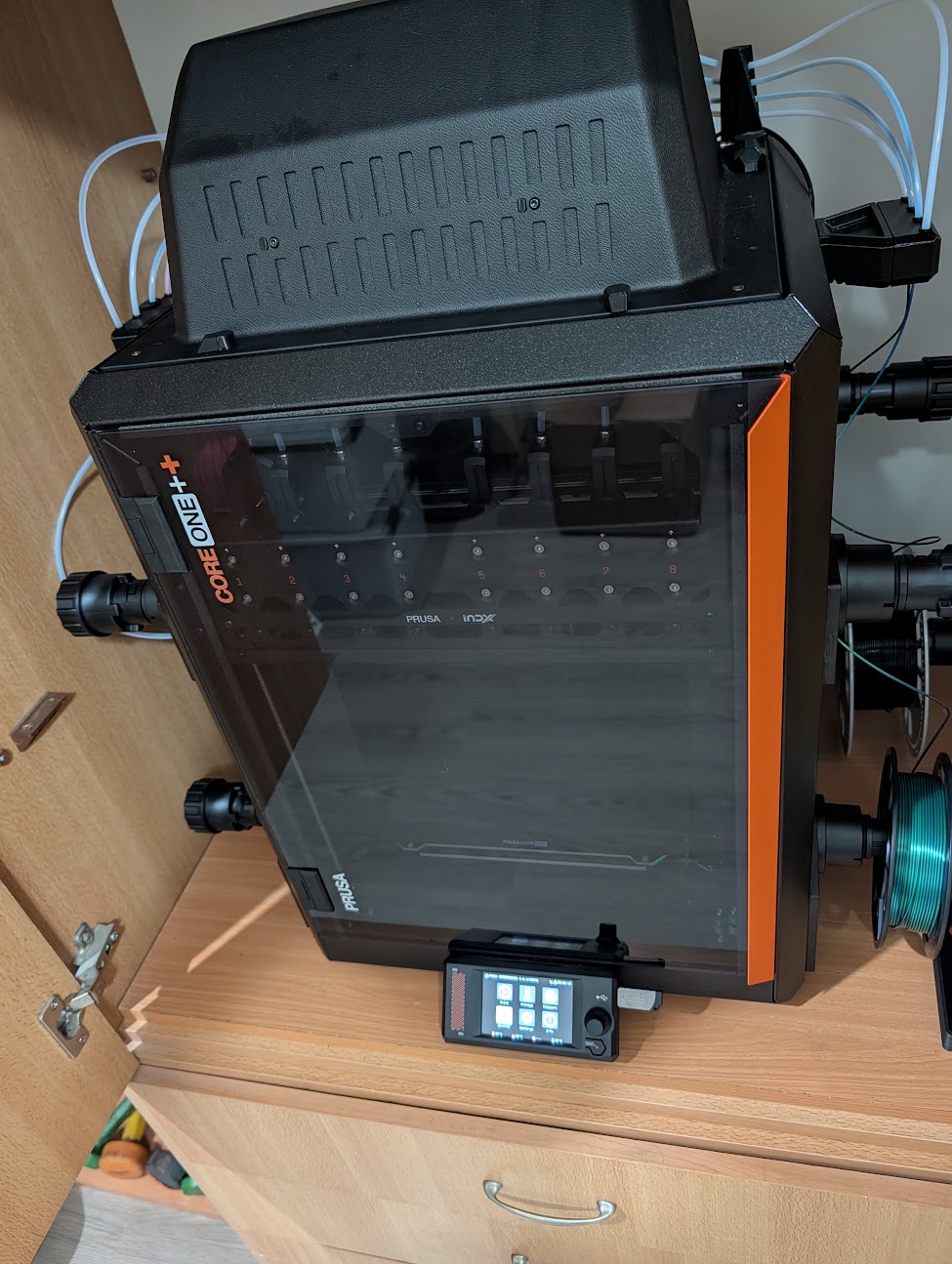
After 2 successful prints, and now knowing that a warm printer is a happy printer, I turned the “serial printing screen” on again to print something AND see what’s going on. The loadcell calibration failed.
I was pulling my hair out when the LLM said that the exact same print succeeded with the serial printing screen off, so we should try that, which made things work again.
I then had it analyze the firmware to see what actually changes with and without serial printing, aside from the printer lighting. The answer was very little, nothing it could suspect, so it said that the LEDs could be a problem.
Being a smart guy overall, I knew this was folly, but had no better lead so I had it flash a custom firmware with the LEDs disabled. It printed perfectly.
We proceeded to separate the different LEDs (4 of them) and try a calibration with every possible permutation (16). The raw result is here (p2p is the peak-to-peak noise the firmware reports on the loadcell while it waits for the reading to settle, OK/NOK are the probes accepted and rejected during the tool offset calibration):
| lit LED groups | loadcell p2p (g) | probes OK / NOK | result |
|---|---|---|---|
| none | 145 | 13 / 0 | clean |
| LCD | 158 | 13 / 0 | clean |
| head | 151 | 13 / 0 | clean |
| chamber | 153 | 13 / 0 | clean |
| LCD + head | 142 | 13 / 0 | clean |
| LCD + chamber | 142 | 13 / 0 | clean |
| head + chamber | 148 | 13 / 0 | clean |
| LCD + head + chamber | 154 | 13 / 0 | clean |
| bed | 238 | 13 / 75 | completed after retries |
| LCD + bed | 218 | 5 / 35 | calibration FAILED |
| bed + head | 240 | 9 / 45 | calibration FAILED |
| bed + chamber | 235 | 10 / 30 | calibration FAILED |
| LCD + bed + head | 227 | 11 / 33 | calibration FAILED |
| LCD + bed + chamber | 242 | 15 / 66 | completed after retries |
| bed + head + chamber | 232 | 14 / 42 | completed after retries |
| all four | 241 | 13 / 27 | completed after retries |
From reading the table, one can see that whenever the bed LEDs are used:
- The number of NOK (not OK) probes jumps dramatically
- The p2p (variance in loadcell’s reading between readings) changes from ~150g to ~240g
- The calibration either fails or barely completes after retries
The runs without the bed LEDs are as pure as snow, and the other three LED groups change nothing either way.
I’m not smart enough with electronics to know exactly how the bed LEDs are affecting the loadcell’s readings, but I reported it to Prusa (prusa3d/Prusa-Firmware-Buddy#5526) and they’ll probably figure it out.
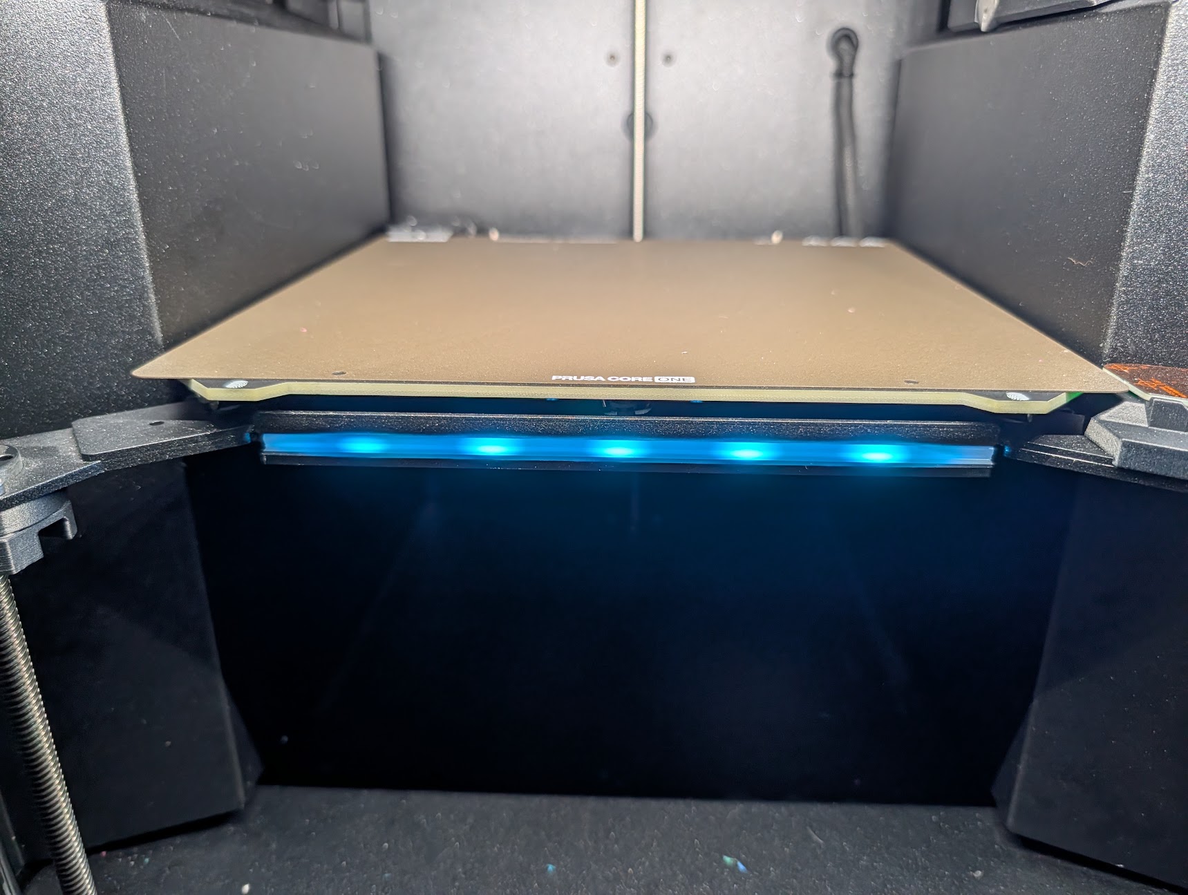
To the best of my knowledge, the LEDs are PWM-operated, meaning that their intensity (and intensity of each color) is controlled by what percent of the time their power is on. Think of it like sending a few hundred pulses a second, where if 80% of those pulses are “1” compared to “0”, the LED is on in 80% intensity. This means that theoretically, these pulses can manifest as noise in another wire or component nearby, and if there’s a component measuring the signal strength in that vicinity, those pulses might affect that measurement.
Those LEDs are not very important - they change their color to indicate what the printer is up to right now, and a quick workaround was to completely disable them during the print. A quick followup was a custom firmware that disabled the LEDs just for the moments the loadcell was in use.
“But do you NEED the LLM here?”
No. I’m a somewhat intelligent, highly motivated, overfocused, tech-savvy person. Given enough time (and help from Prusa support), I would have tackled all of these successfully.
However, having the ability to query against the guide and the firmware effortlessly, asking garden variety questions about electronic components, and being able to quickly churn out new firmware versions and testing scripts provided a lot of utility and shortened the time for me to get to a working printer.