A couple of months ago, I had my HVAC controller replaced in an effort to save on electricity.
I controlled the previous board with an IR blaster that I loaded with a full matrix of {mode,fan_speed, target_temp} (and a special command for “off”). The new one didn’t work like that.
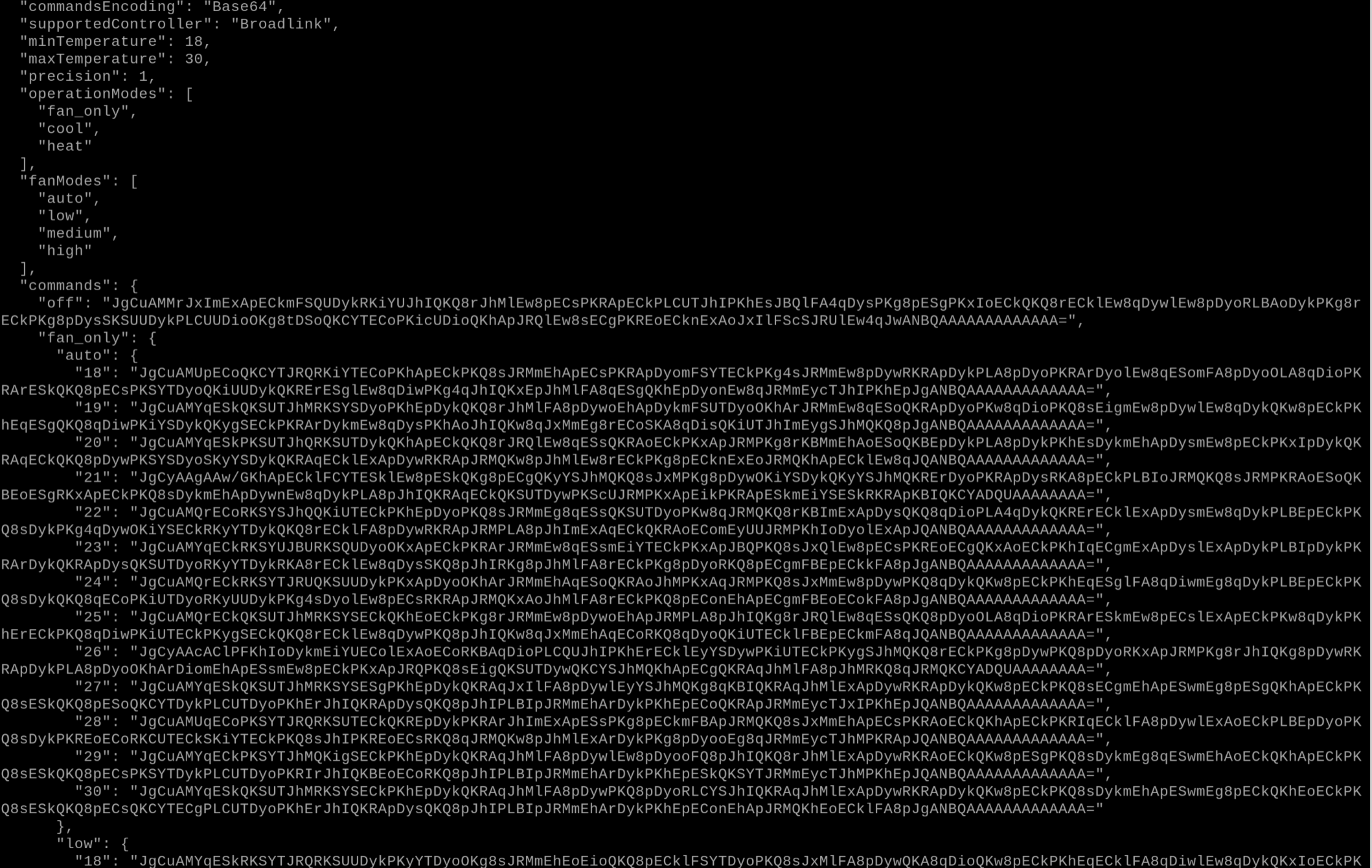
The old blaster’s config: one recorded Base64 blast per {mode, fan, temp} combination
No “off” button
The new remote/controller dialect had no designated “off” command. Instead, it had a “toggle” command, which makes the AC off if it’s on, and on if it’s off.
It sounds innocent enough when it’s a remote button, because an observer knows whether the AC is currently off or on, and therefore whether it needs this button to get to the wanted state. For a smart home solution, it was a problem.
If the AC is currently off and I want it set to “cool”, I will need to send a toggle command. However if it’s already on (e.g. fan only) and I send a toggle command, it’ll turn off.
This meant I needed a way to get the AC’s current status in order to decide which command to send.
Reading status is important
The original controller for the AC had no external indication for what it’s currently doing. The “external entity” was a small plastic with a single LED, a single button (on/off toggle) and an IR receiver. It obviously had an internal state (cool/heat, target temp) but didn’t expose it in a way I could read, so my best course of action was remembering the last state I sent it and assuming it landed. It wasn’t perfect, but it worked.
The new controller had a fancy LCD screen
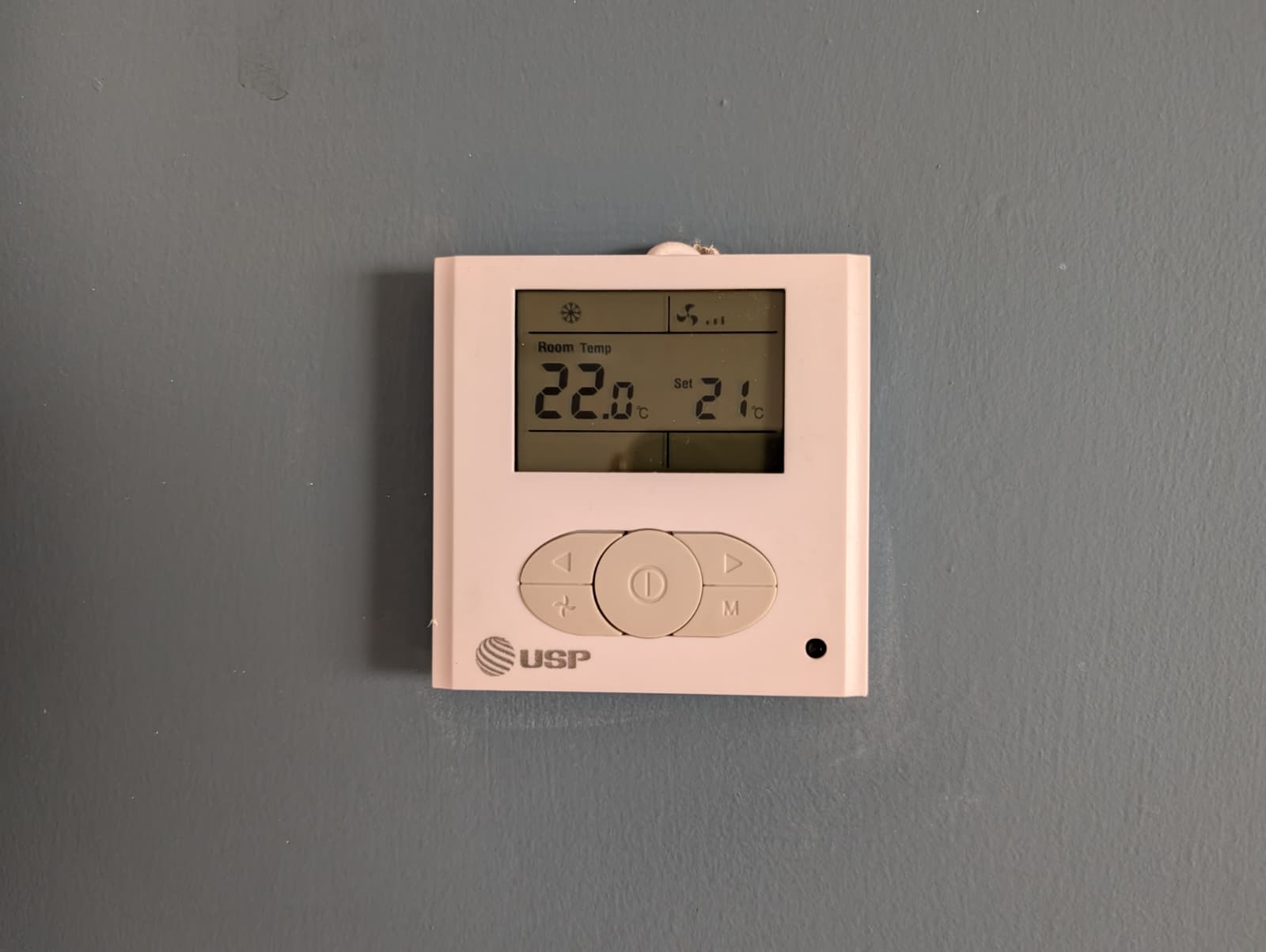
It showed exactly what the AC was thinking, including the part I desperately needed - whether it’s on or not. Knowing that will let me decide whether I need to send a power toggle with a new command (off->on, on->off) or not (on->on but something else).
Naive idea
My original plan was this:
- Put a device between the controller and the panel
- Learn the secrets of how they communicate
- Create a device to permanently tap that channel and read/write AC state
Which sounds good, if you discount the fact I know very little about electronics or signaling.
1. Cutting things
I bothered my HVAC tech enough to learn where they buy their electronics and got myself another HVAC controller (~50$), fully expecting me to destroy some components during my experiments.
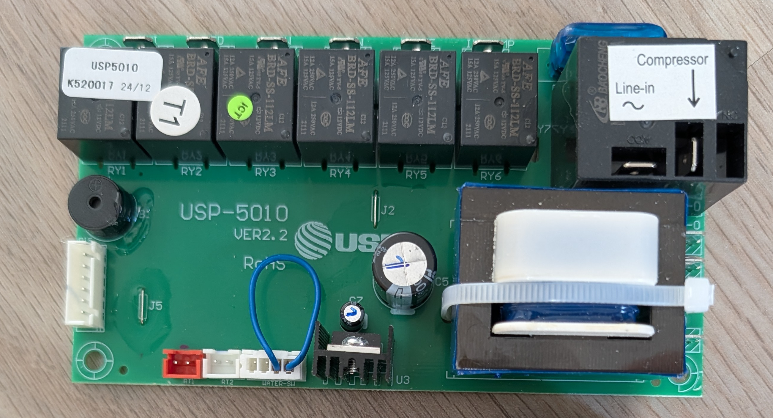
The spare HVAC controller. I only care about the white connector on the left.
I disconnected the nice installed LCD panel and connected the spare one, which was placed on my crafts desk.
I cut the cable and started probing it with my multimeter to find it’s 5v. I then consulted a friend who did some hardware reverse engineering.
2. Wiretapping
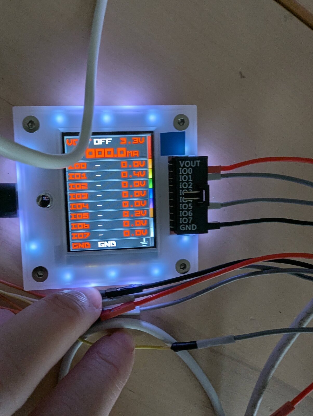
The friend recommended I get “some hardware you can use to listen in”. I had several Arduinos, but they weren’t good enough. I pushed back against getting an oscilloscope and we settled on a BusPirate. It’s small, programmable, designed to help you crack protocols on other people’s electronics. I chose BusPirate 5, which is not the newest, but probably enough for me.
I thought I was really clever by doing the following:
- Splice the BP to the LCD cable, connecting both it and the LCD panel to the controller in a way that showed the data on the BP while keeping the LCD panel working
- Connect the BP over USB to a Raspberry PI I had lying around, and setting wifi+ssh on the RPI.
- SSHing to the RPI from my laptop, so I don’t have to sit next to the very touchy wires
- Opening an account for my friend so they can remote-ssh to the RPI, doing whatever debugging they want
This entire procedure took way way longer than it should have (about 7 work days).
One of the blockers was that the protocol is not standard. e.g. it wasn’t SPI or I2C.
The other was that I connected the wrong cable to BP’s ground wire, meaning it got garbage readings.
During this time of despair, I told my friend “what if those engineers at $COMPANY built a really sophisticated protocol? What chance do we have against the smart people in the lab?”
He replied with “as much as you think you don’t know about electronic signals, these guys don’t know either. They’re not here to reinvent the wheel, they’re here to get something working and move on”.
After that, I found the bad wiring and immediately made progress. My friend was right.
3. Protocol basics
BP was running in “logic analyzer” mode, being connected to sigrok / sigrok-cli on the rpi to read the inputs.
At this stage my friend was bored (“it’s just the bits now”) and I needed another partner, so I got Claude Opus (4.5 I think) to help me. I gave it unfettered access to the rpi over ssh (because it was isolated and had nothing of significance on it) and told it to go wild with analysis.
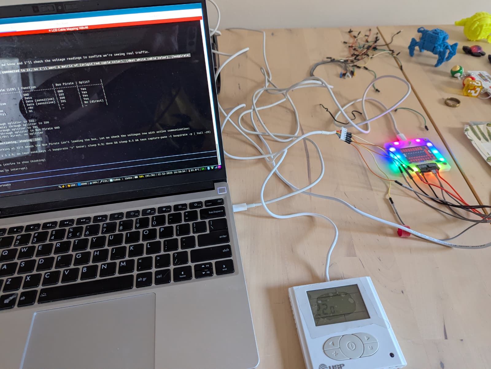
Together, we produced the following bits of information:
- There are 5 wires. Two of them were GND and +5V.
- One wire had no activity, unless I was sending IR blasts from the remote. We deduced that this is a dedicated IR line.
This made sense to me because the controller supports secondary “heads” that only have a led and IR receiver, so it makes sense that IR is not part of a complex protocol. - Two wires contained some sort of activity. One was rhythmic, and we’ve decided it’s a clock line. The other had rises and drops that somewhat correlated to the clock rate, but contained more variability. We’ve decided that one is data, and the entire protocol is SPI-like (although not full SPI).
The data was repetitive enough that we could identify repeating patterns (hereby declared “frames”), although we didn’t know what they contained.
4. The ultimate contraption
I already had an authoritative source for what the frames contained - the LCD screen itself. I started with recording frames and manually labeling them with what the lcd panel said at the moment, but it was manual, slow, boring. I decided to automate, and involve as many “things I have lying around” in the effort.
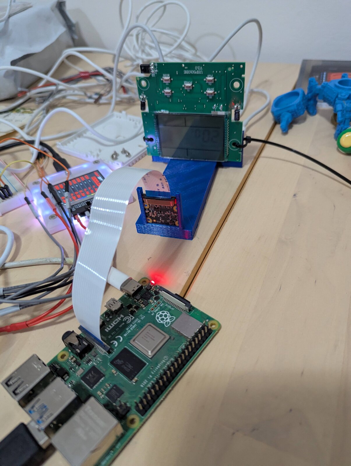
- I 3D-printed a “camera-screen mount”
- The LCD panel was zip-tied to the mount
- A breadboard connected the LCD panel, the BP and the HVAC controller together
- A rpicam was mounted to the mount, pointing at the LCD panel (and focused correctly)
- The rpi was connected to the rpicam and the BP
I wrote a tiny script that ran on rpi that did the following:
- Take a picture of the LCD screen
- Record a full buffer-worth of buspirate via sigrok-cli
- Take another picture of the LCD screen
- Run some poor man’s computer vision on the LCD screen pictures to grab the following:
- room temperature
- target temperature
- mode (cool / heat / fan only), fan speed, whether compressor is running
- If any of the pictures don’t parse well, or disagree (indicating a change in the middle of the recording), mark the packet as garbage
- Otherwise, create a small metadata.json to label the recording
I ran this script on several different configurations and let it run for several days in a cronjob.
I handed all of the recordings to Opus and had it do some disassembly work.
It succeeded.
Opus was able to create a script that grabbed a BP dump and deterministically extracted the current HVAC status from it, which indicated a success on the reading front.
For instance, we noticed two kinds of frames - one 76-bit long coming from the controller indicating state, and another “poll” frame that involves the controller asking a question, then leaving 36 bits of quiet for the LCD panel to report back (I assume button presses are reported in that window), all happening on the same data line.
5. Time to write
Now that we covered the read path, we could tackle writing. I had two options for writing:
- simulating LCD panel keypresses, which let us cycle mode / fan speed, change temp -1/+1, toggle power
- Copying the remote IR blasts, which contained full state (with a possible power toggle)
I chose to ignore #1 because it was a subset of #2. BP was not designed for writing, and I had to find another gizmo for doing the writes. Luckily I had all of those Arduinos.
I really wanted an ESP32-based solution because I know how to program them and my devkits had wifi, but ESP32 runs its GPIOs on 3.3v and the HVAC was doing 5v. While this isn’t magic-smoke-level incompatibility, it will ruin the ESP32 over time. Arduino doesn’t have the problem as it runs on 5v, but it doesn’t have wifi.
I started with an Arduino Uno, getting commands over serial from the rpi, and graduated later on to an Arduino R4 I found, which is both 5v and has wifi (which let me control it via MQTT).
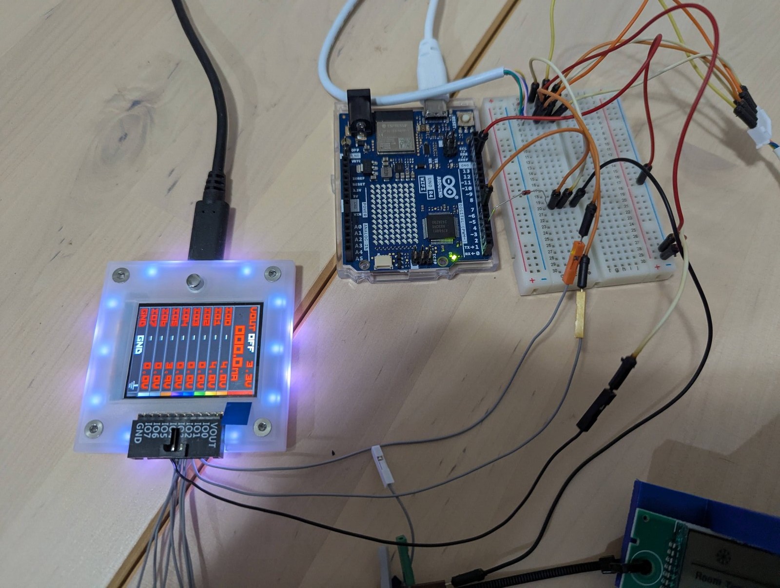
I didn’t do as much IR decoding as I did IR recording at this point - I connected some IR receiver to the Arduino, recorded a blast, then replayed it on the IR line and checked the data before/after to see the HVAC state change.
This helped me build a capture script that does the following:
- Record IR blast
- Grab HVAC state before
- Play IR blast
- Grab HVAC state after
- If before and after are different, categorize IR blast as generating the “after” change
I built a healthy matrix of {mode,fan_speed, target_temp, is_power_toggle} and had Opus work hard on the captures to reverse engineer the protocol.
6. Decoding IR
I gave Opus permission to craft all sorts of weird IR sequences and send them at the controller, each session provided value.
The biggest discovery was Opus finding out that it’s not only about bits sent, but about cadence.
A logical first step the LLM did was converting the BP dumps into “the bits the IR transmission contained”. While it was able to reproduce some state changes, it couldn’t do others. Even more confusing - some state transitions looked the same, but evidence showed they pointed to different states.
Once Opus turned around to compare the raw recordings, it found that the duration of the waves making those 1s or 0s was different, and keeping that as part of the blast resolved matters.
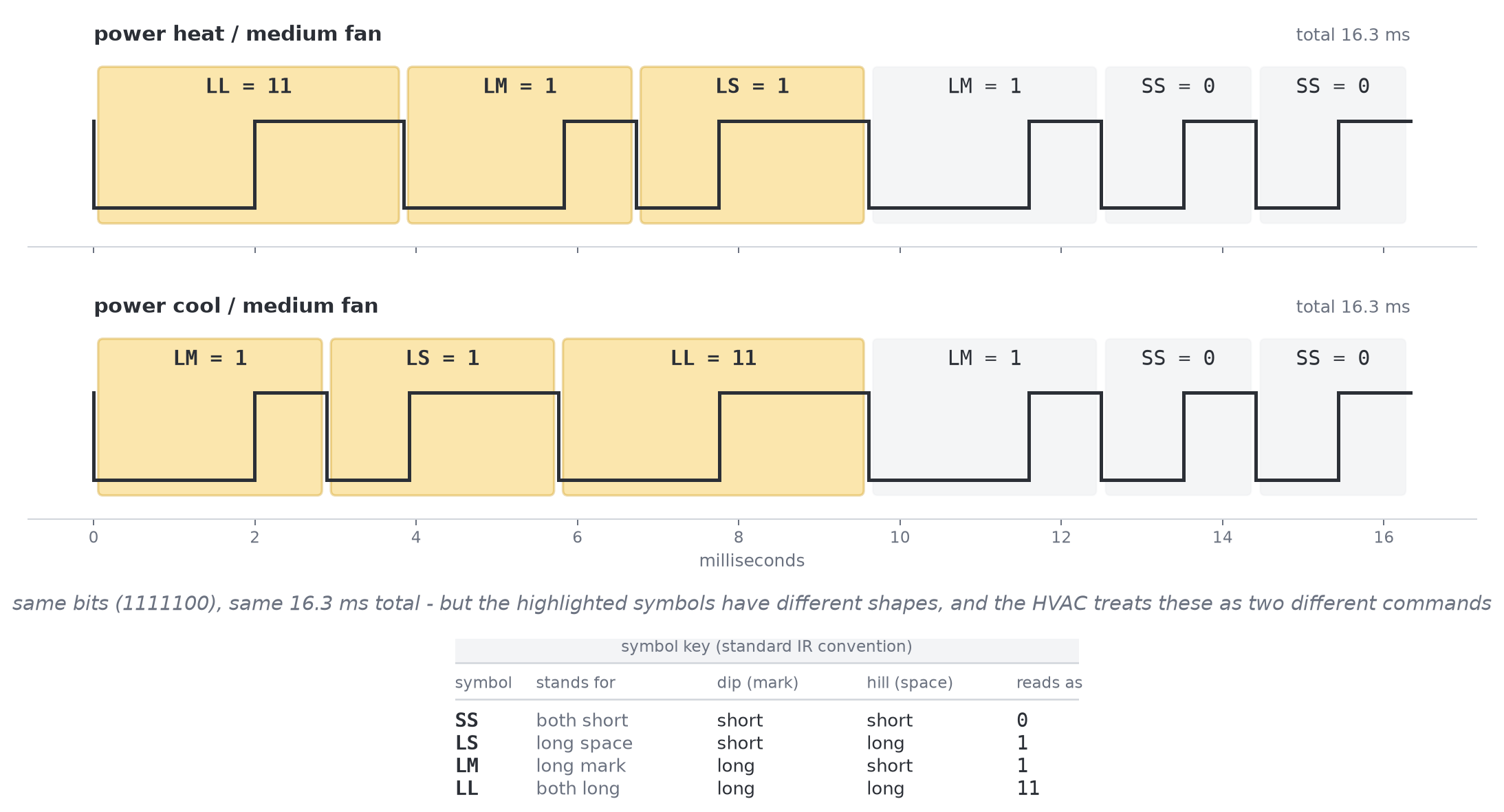
I, personally, as a non-electronics-signals-person, do not understand the value of playing with the duration. However, I’ve confirmed with some more savvy friends that this is indeed standard practice (“pulse-width encoding”).
7. Hardware o’clock
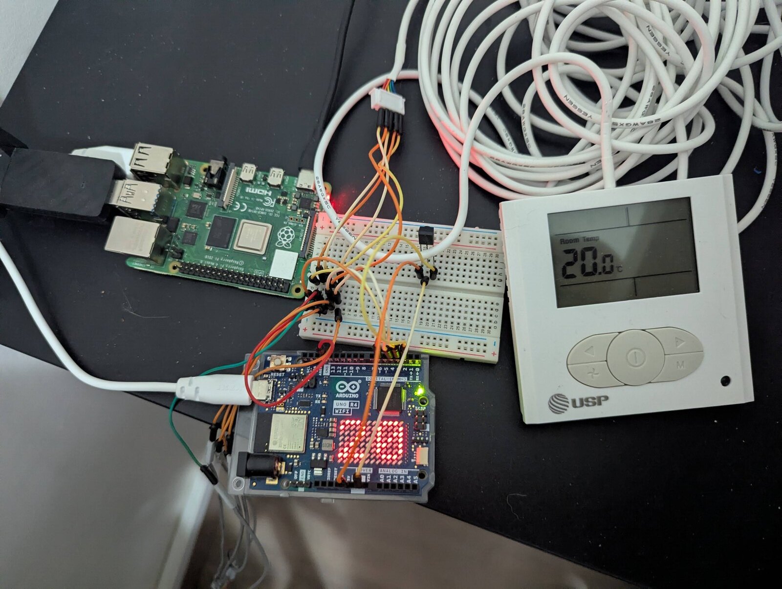
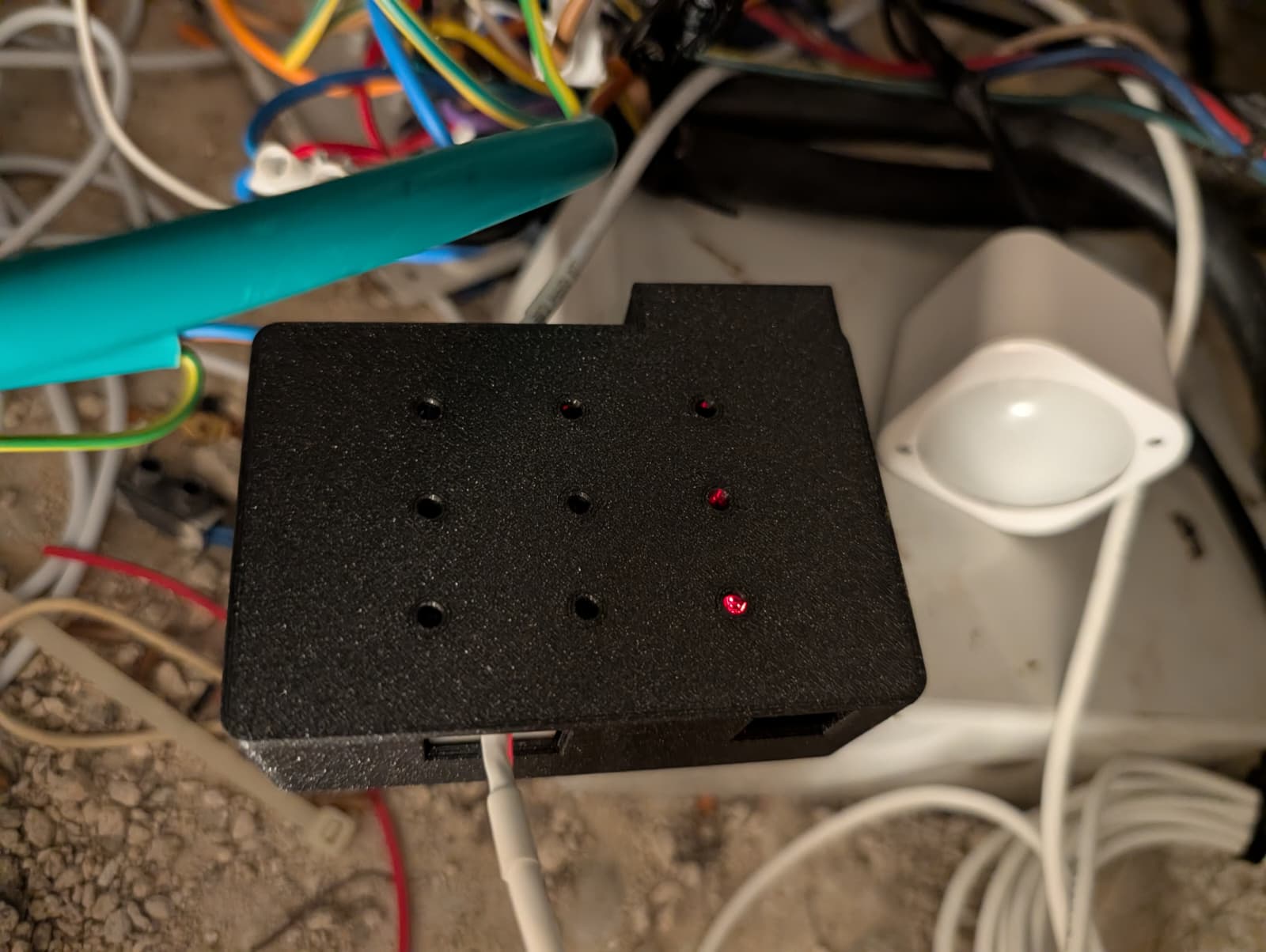
Arduino R4 doing both reading and writing, accessible over WiFi. The rpi allows “OTA” since R4 didn’t do it nicely. The R4 matrix shows the room temp because LED matrixes are fun
Getting read/writes was great, but I wanted to find a solution that doesn’t live on my desk (and has a bunch of delicate wiring). I contracted Opus to design a PCB that will live next to the HVAC controller in the attic.
Our design constraints were these:
- The 5v on the AC’s cable is too weak to feed an ESP32, so we’re going to need to get mains power and convert to 5V for internal use
- The ESP32 is operating internally on 3.3v, so we’ll need some sort of adapter between it and the HVAC wiring
- I hate doing UART for flashing, so I want USB flashing, and OTA if possible
#3 was easiest to resolve. I decided to take ESP32 devkits (as opposed to wired on the board), which also let me switch them between PCB iterations (and in case I burn something).
#1 made the PCBs a bit more expensive (and dangerous because mains) but overall doable.
#2 was a cause of so many problems.
The development flow was this:
- Opus builds a textual spec in markdown, possibly a list of changes from the previous iteration
- I find someone on Fiverr to turn this into a proper PCB schematic and BOM
- Send those to JLCPCB for fabrication
- When it arrives, test the following:
- Powered by USB, connected to HVAC cabling
- Powered by mains power, connected to HVAC cabling
- Assuming everything works, install at the attic
The true winner of the JLCPCB shipment
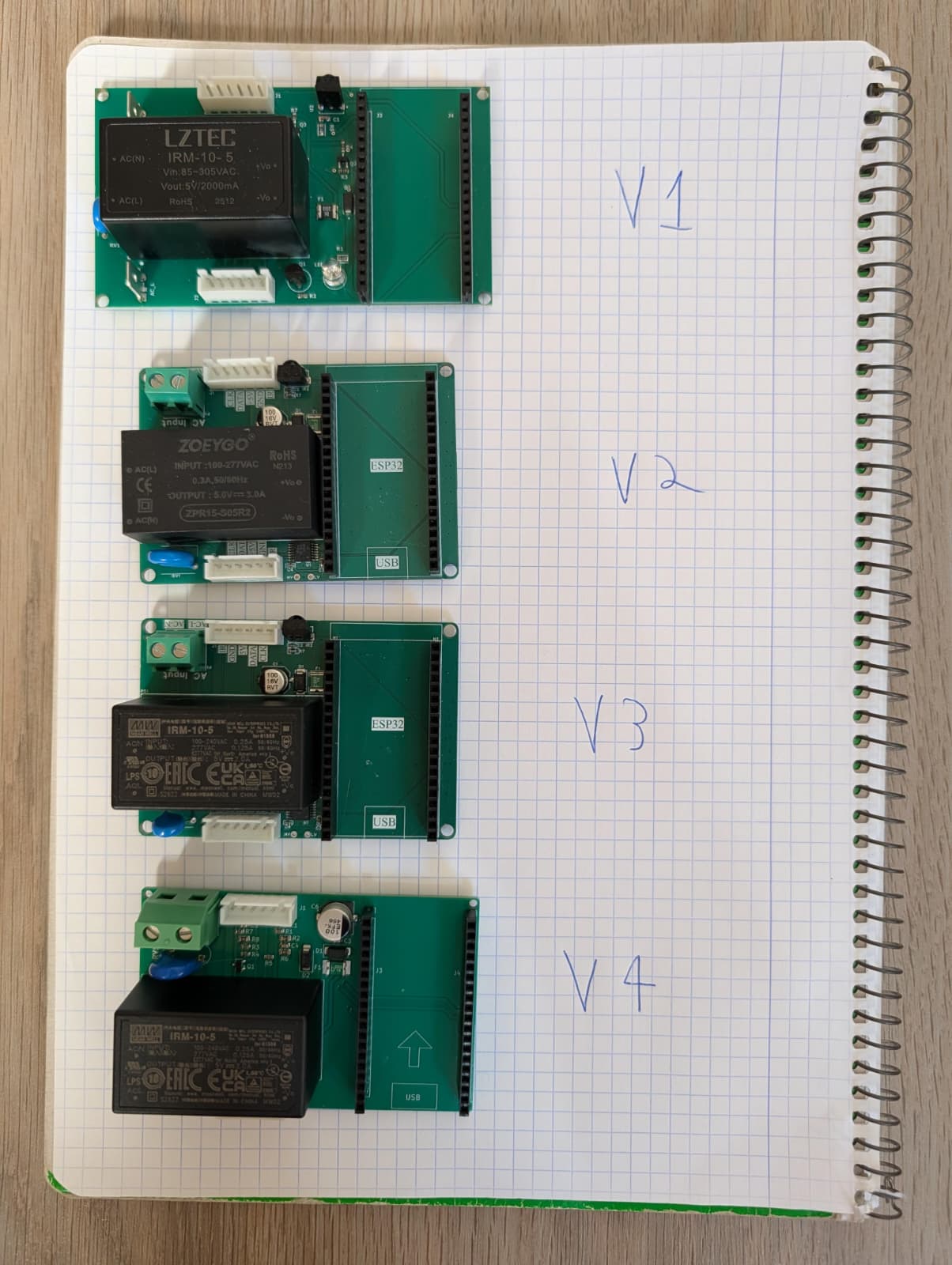
I had 4 different iterations, and the failures came pretty early.
8. Hardware iterations
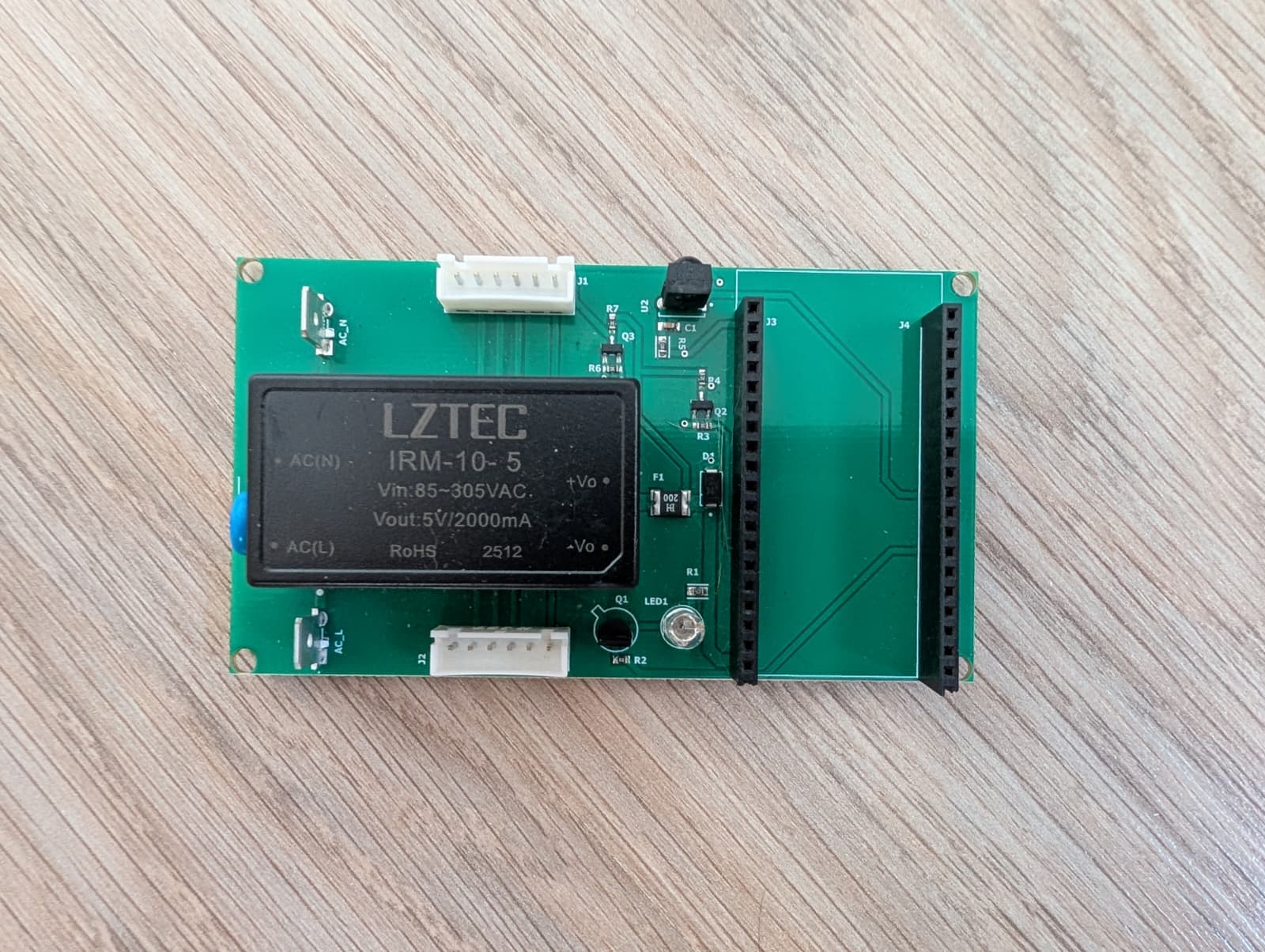
V1 was naive about GPIOs and failed when the ESP32 was seated. It wired the AC’s clock wire into ESP32’s gpio 12, which was a strapping pin. The 5v-3.3v level shifter had “HIGH” as default (no input), meaning gpio 12 was enabled, instructing the ESP32 to treat its flash storage as “requires 1.8v to operate”.
Well, the flash doesn’t work at 1.8v, it’s built for 3.3v, so fed with 1.8v it returned garbage, causing the ESP to reboot, again into “flash 1.8v” mode, putting us in a perma-boot-loop.
The level shifters also had something wrong. Even without any ESP32 present, they generated noise that corrupted the data lane, causing the screen to display garbage.
At the time, I thought the problem was also “level shifter being too slow” (shows just how much I know what I’m doing, the bus itself is pretty slow at 7.1kHz), and decided we need “faster and therefore better” ones.
Lastly, I also seated one ESP32 devkit the wrong way around, magic-smoking it.
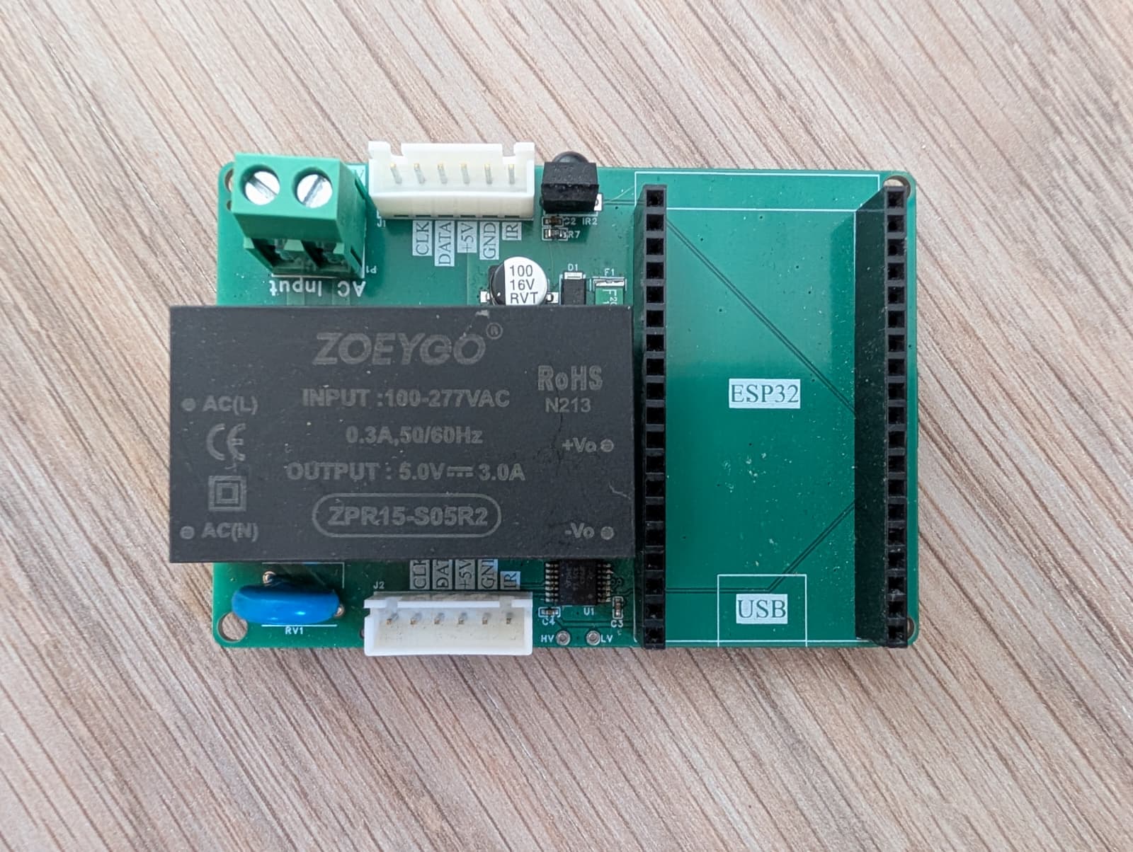
V2 shuffled the GPIOs around to prevent bootlooping, and added an indicator for which direction the ESP32 should go in, so no more magic smoke.
It did reverse the HVAC cable pinout, meaning I had to mangle the plastic receptacles to do basic testing.
The ESP32 now had multiple sources of power (mains power, HVAC cable) that were all bridged with each other, meaning that either the ESP32 was leeching power from the LCD panel (that died whenever wifi was established), or polluting the HVAC data with power oscillations.
As a side adventure, playing with the HVAC cable’s positioning while the device was connected to mains power gave me a painful shock - luckily it was just one finger closing the circuit, and only for a moment. It convinced me to not mess around with mains power myself (don’t be an idiot like me).
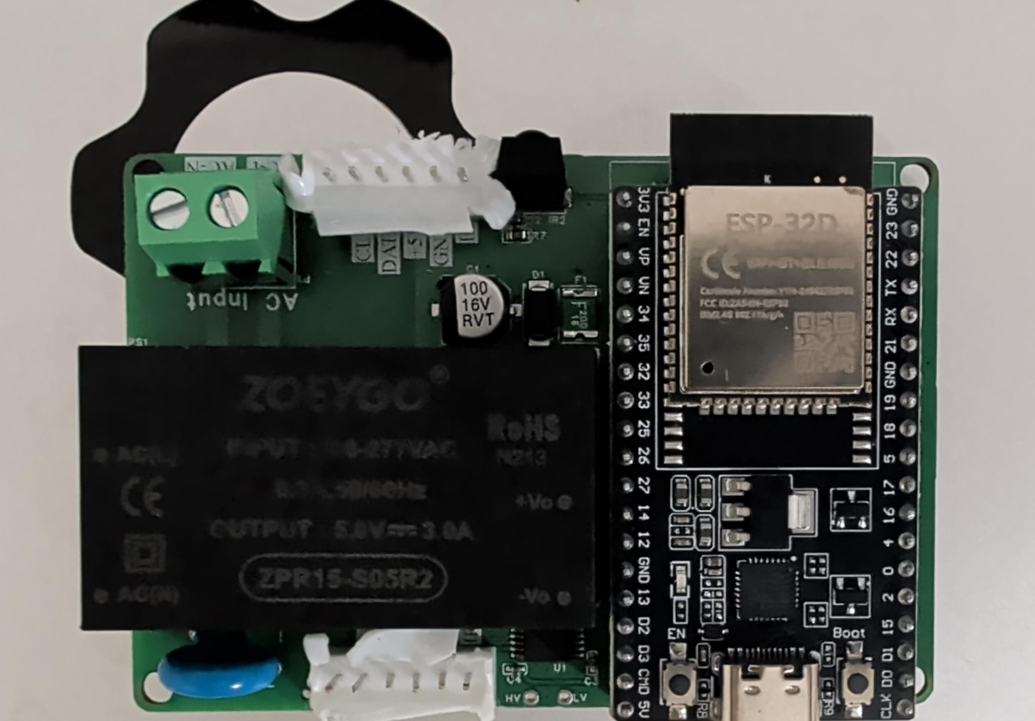
Despite all of this, I was able to tell something was still wrong with the hvac-esp32 connection. When powering the esp32 from its USB socket and trying to read the HVAC state, I got more clock ticks than I expected.
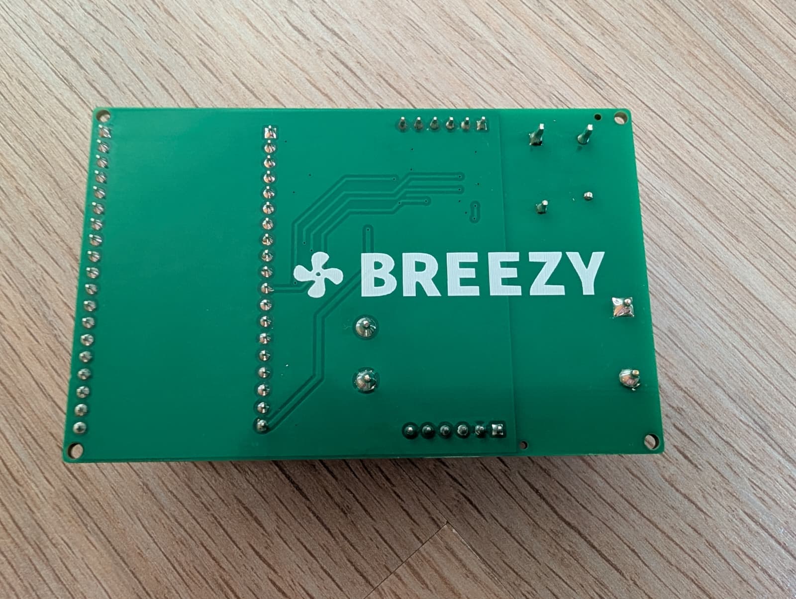
Just for fun, I added a name and logo for the silkscreen of the back of the pcb. Called it “Breezy”.
V3 fixed the power mingling and the wrong pinout. No problem, no complaints.
The clock ticks I tried fixing by adding a resistor and a capacitor (100 Ω, 100 pF) to reduce noise I suspected was amplified by the level shifter. This didn’t work. Instead, the screen alternated between displaying an error and claiming the current room temp is -9°C (below freezing), which was not the case. It was provably involving the shifters/ESP32, because when unseating the ESP32 kit, the LCD screen went back to normal.
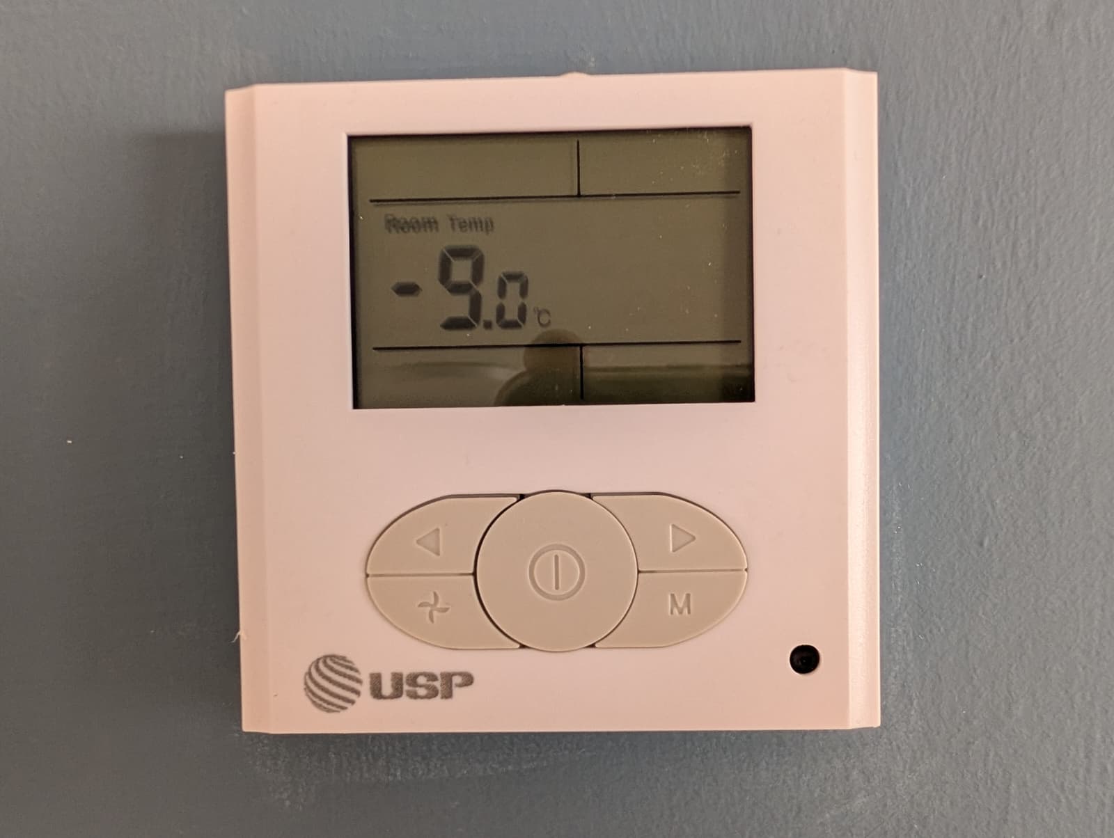
Room Temp: -9.0°C. It was not.
I was a bit lost, as my knowledge about level shifters was exhausted. Then, Claude Fable came out.
Friends told me how much better it was at “difficult problems”, and I figured I’d spill my free credits on this conundrum.
I’m unsure whether Fable had more electronics knowledge, or it can be credited to a new deduction model, but Fable said the level shifters were the absolute wrong tool for the job and suggested something else.
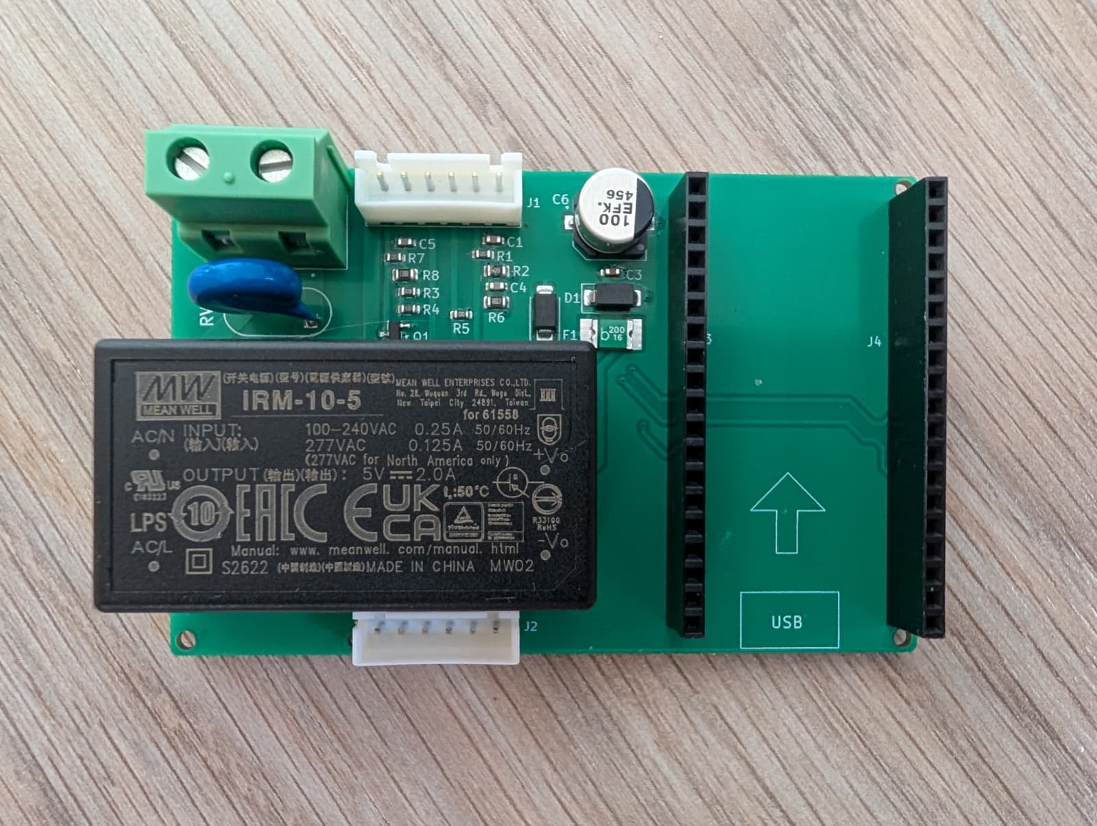
V4’s dramatic change was removing the level shifters.
Fable’s angle is that bidirectional conversion of 5v to 3.3v requires level shifters, which adds complexity and bug-shelters that we don’t need. If we switch to unidirectional reads/writes, we can trade those active components for simpler passive ones.
For reading, a pair of resistors reduces a 5v range into a 3.3v one. lows stay low (zero), and high 5v becomes high 3.3v. No active component that can generate noise, or round edges, or be too slow.
HVAC wire (5v) ─[100KΩ]─┬─ ESP32 pin (reads ~3.2v)
                        │
                     [180KΩ]
                        │
                       GND
For writes, because the signaling method is “active low” (meaning that “nothing” is 1s and “something” is 0s), the ESP32 only needs the ability to set the line to 0 when it wants to. For this, a transistor was enough. It would do nothing on its own, and when instructed it would write “0”.
Our design has us reading and writing the IR line (because we want to be able to learn new IR commands if we need to without the BusPirate), so the solution is to connect the IR line twice, to two different GPIOs. Once with a resistor as a read line, and once with a transistor as a write line.
This worked perfectly. I ran the following series of tests:
- Connect the pcb to the hvac controller and panel, no power or esp32 seated. LCD screen worked.
- Same with ESP32 seated, but no power. LCD screen worked.
- Same with usb power for the ESP32. LCD screen worked, and ESP32 able to read the state and send IR.
- Same with mains power instead of USB. LCD screen and ESP32 work. Device doesn’t overheat.
- Installed in the attic with a usb powerbank. Worked.
- Electrician-installed in the attic with mains. Worked.

9. ESPHome
Before installing Breezy in the attic, where it’d be hard to reach, I flashed it with ESPHome and tested its OTA capability.
This let me continue development without having hardware and cabling littering my desk.
Reasons I like ESPHome for this kind of project:
- Great Home Assistant integration
- Blessed toolchain - no need to hunt for libraries
- Support for USB and OTA version upgrades, with reasonable security
Boring, works. No complaints.
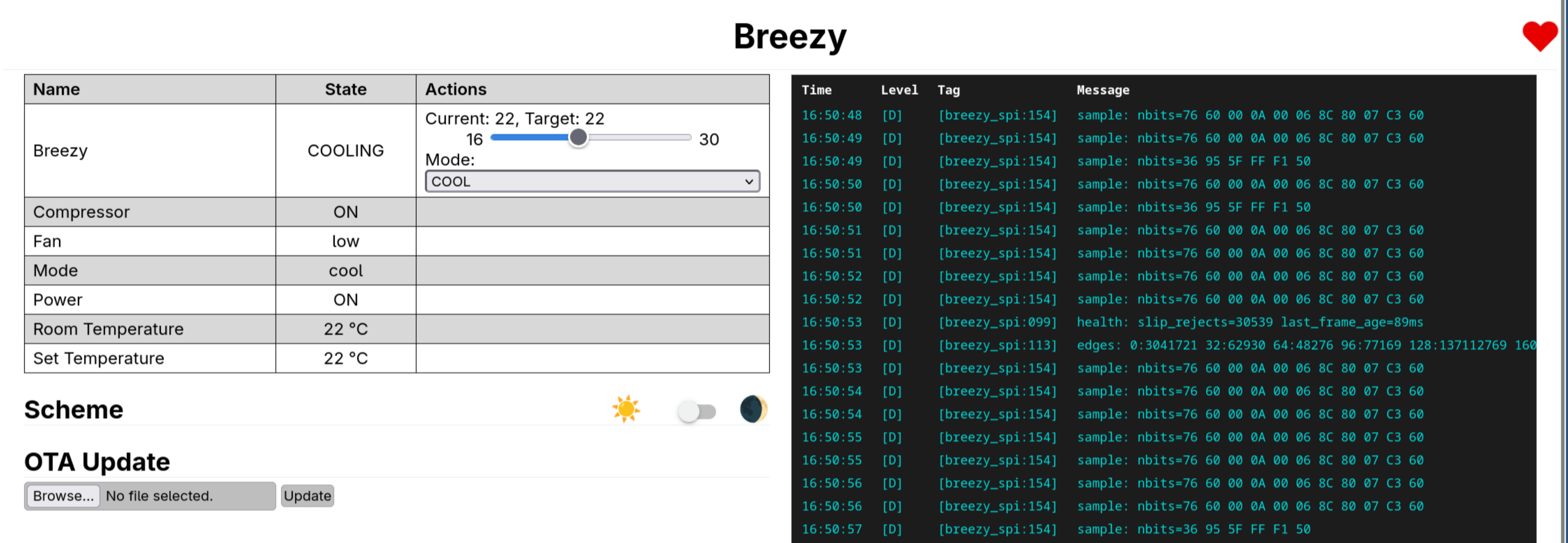
Entity states on the left; on the right, the actual bus frames scrolling by - the long ones are the controller announcing its state, the short ones are it polling the panel’s buttons.
10. Case
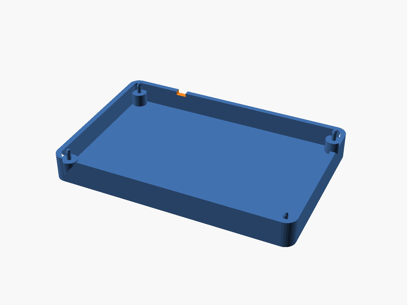
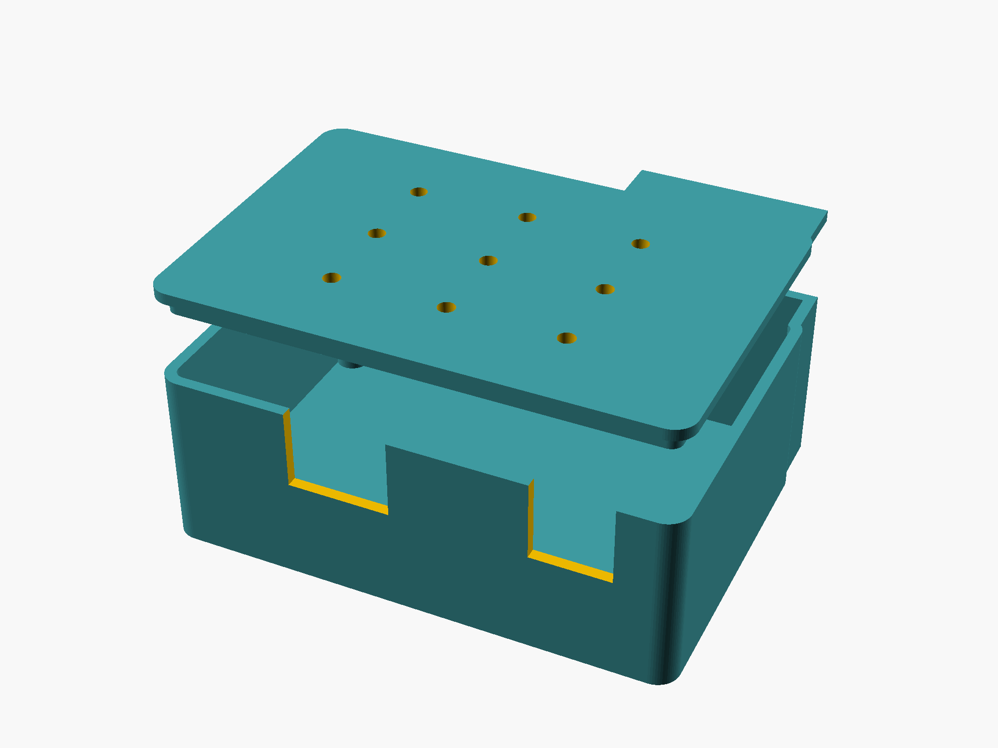
The reason I got shocked is grabbing the PCB’s body when messing with the mangled V2 cable socket, accidentally touching the backside of the mains voltage socket. To stop this area from being exposed, I designed both a small tray (for testing) and a full box (for attic-time) for the case.
Printed out of PETG, works well.
11. Full decoding and the hardships on the way
Even when I had Breezy installed in its final position (by a professional electrician!), I continued working on decoding both the read and write protocols.
They both fed into each other to let the LLM test things mostly independently.
For instance, each IR blast repeated the same exact message 3 times, which I assume was for redundancy, since IR is not a 100% reliable medium (strong Pokemon-trading-over-IR vibes), so the LLM sent an “IR” blast (quotes because it was actually over the wire) that composed only two frames. This was not accepted, and neither was trying to get the ESP32 hardware to repeat the frame 3 times, as opposed to loading all 3 frames as a very long byte sequence.
We overall did a lot of experimentation over our IR commands being occasionally ignored. We had some theories, like “the HVAC controller is busy doing compressor things and is ignoring us then”, or “it needs multiple repeats of the same 3 frames”.
Turns out we were not being ignored at all. Instead, I had two problems:
- I forgot that the ESP32 is not a full fledged computer. I kept its tiny CPU so busy with IR retries and dumping debug data into websockets, so that it didn’t have enough time to listen and parse the state packets from the HVAC controller.
After realizing that, I reduced logging dramatically. If I ever need very detailed logging, I’ll get another Breezy set up (I have 5, as it’s the minimum amount for JLCPCB fabrication), or bring the BusPirate out of retirement. - The state reader was over-strict on frame validation.
It decided that a certain area (e.g. byte #3) was supposed to be 0, and discarded any frame where this wasn’t the case.
In retrospect, there’s probably a bit there indicating whether the LCD backlight should turn on, which happens for a couple of seconds after a valid IR command is accepted. All of the dumps came from backlight-off durations, meaning this byte was 0, so the LLM decided that this byte should always be 0.
Ironically, this made it reject any frame happening after a valid IR command, meaning the new state was not accepted, causing us to retry the IR transmission, getting some more backlight frames, causing us to retry again, and so on.
Other enhancements and discoveries we did post-installation:
- Some items, like “target temp 24c” or “mode heat, medium fan” can seem like 7 bits instead of 8, which didn’t make sense to me.
Further testing showed they’re all 8-bit, but looked like 7-bit when decoded wrongly. - Power toggle frames are different in structure from the non-power-toggle ones, but contain the same data, meaning we could kick the HVAC directly to a specific state (no need for a power toggle and then sending the new state).
LLM says that making the power frame drastically different than a regular one prevents a random bitflip on a regular frame turning the HVAC off. I don’t have enough understanding in signals / electronics to have an opinion here. - The state protocol’s checksum was understood, and we switched from “majority vote” validation, as in choosing the most-repeated state within a second as the HVAC’s true state, to validating via the checksum.
We needed that because the captures, although good, were not perfect
12. Public repo and future work
I uploaded all of the usable parts to a repo (Backslasher/breezy), so if you happen to have a “USP 5010”, you can make your own.
If you don’t have that model but you have something similar enough, you can probably copy a big bunch of my work. The ESP32 read/writing 5v was very annoying and I hope to reduce the amount of pain it causes other people.
The actual v4 of Breezy works well. I have a list of future requirements for v5, but it only has one item, and I’m not sure it’s needed (“allow writes to data to emulate LCD screen keypresses”).
Overall very happy with this.
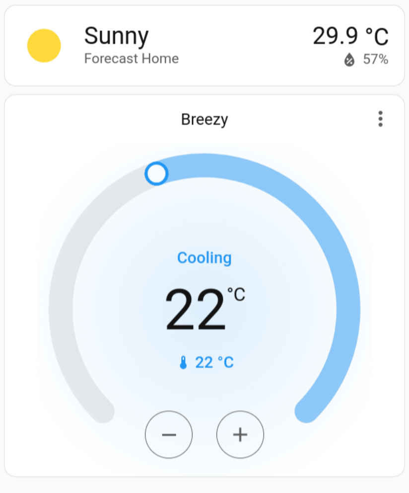
29.9°C outside, 22°C inside, actively cooling.